← All productsPressure and airflow control · STG line

STG CPD

Pressure under continuous control, airflow by K-factor. Built-in pressure sensor and two digital inputs for the filter pressure switches.

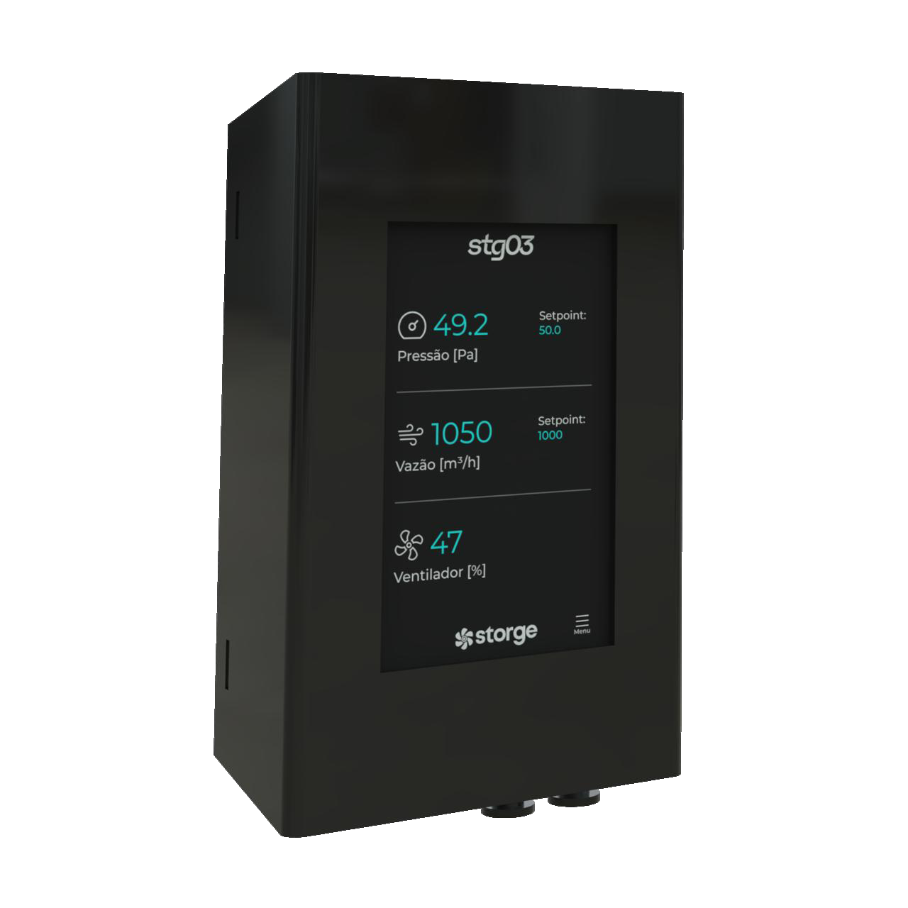
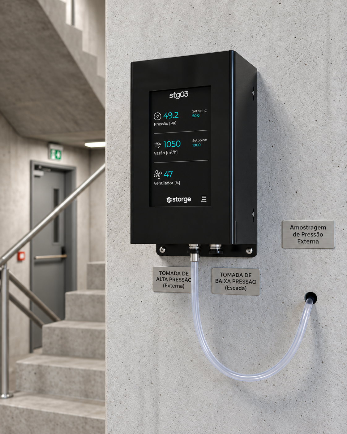
STG CPD, black enclosure with 4.3-inch display
MeasuresDifferential pressurebuilt-in sensor, + and − taps
CalculatesAirflow by K-factorfrom the pressure and the equipment's K-factor
Monitors2 digital inputsindividual status of the filter pressure switches
CommandsModulated fanthrough a compatible drive, according to the motor
How it works

Two circuits, one controller.

The built-in sensor handles pressure or airflow control. The external pressure switches, wired to the digital inputs, report the individual status of each filter.

Circuit 01 · Control

Pressure and airflow

Continuous measurement by the built-in sensor. Direct pressure control, or airflow control from pressure and the configured K-factor. The fan is modulated through the compatible drive.

+−
Differential pressurepneumatic taps
measures pressure
STG CPD
STG CPD controlspressure directly or airflow by K-factor
commands the drive
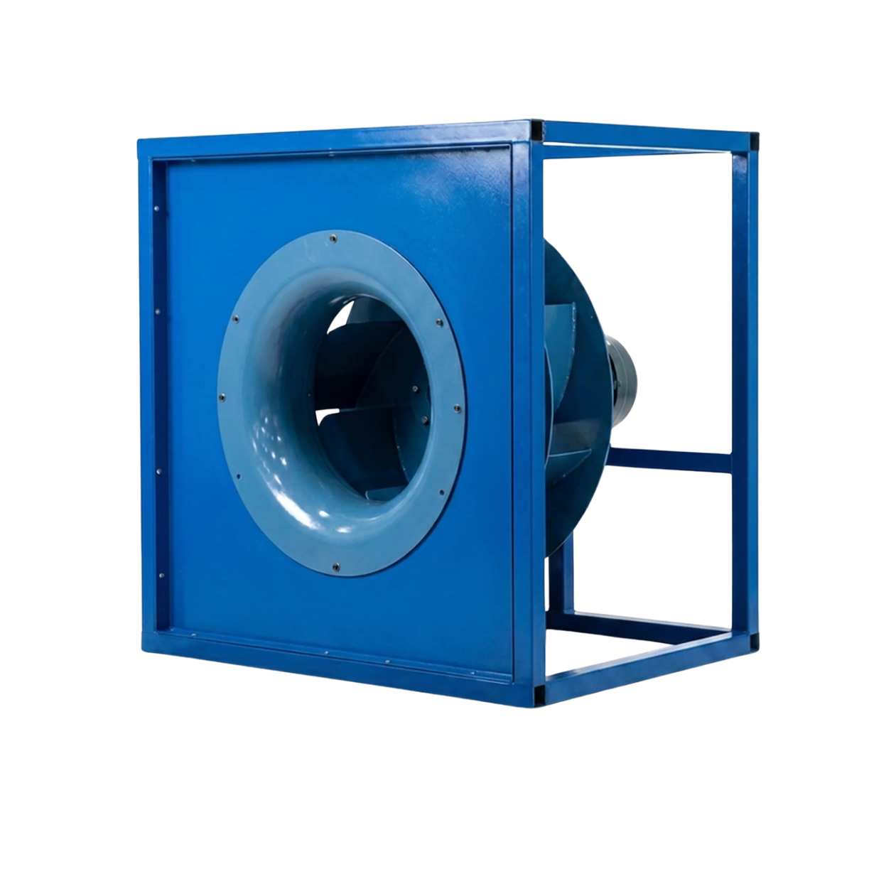
PF radial fan
PF radial fancontinuously modulated
Circuit 02 · Status

Filters, one by one

Two external pressure switches, one per filter, wired to digital inputs 1 and 2. Each input identifies its filter; an airflow performance alarm complements it, without locating the filter.

DI 1Pressure switch
of filter A
DI 2Pressure switch
of filter B
digital signal
open / closed
STG CPD
STG CPD
Filter alarms
Per filter

The pressure switches on DI 1 and DI 2 indicate each filter’s saturation, with indication and alarm per channel.

By performance

If airflow does not reach the setpoint within the configurable time, the CPD alarms possible filter saturation, without identifying which one.

The digital inputs receive the pressure switch states; continuous pressure measurement comes from the built-in sensor. Pressure switches are external devices and are listed in the commercial scope.

The same controller

One board, four ways to control differential pressure.

The same STG CPD that pressurises the stairwell serves the other cases where differential pressure is the quantity to control.

  1. 01Constant airflow

    As the filter gets dirty, pressure drop rises and airflow tends to fall. The controller detects that variation and automatically adjusts the fan speed to return to the desired airflow.

    • Same airflow with a new or dirty filter
    • No manual adjustment at every filter change
    • Design airflow verified on site
  2. 02Clean room

    Keeps the clean room at positive pressure relative to the neighbouring areas. The controller reads the ΔP between rooms and corrects the supply air to return to the desired pressure.

    • Positive pressure between rooms
    • Continuous correction, no manual adjustment
    • ΔP logged for validation
  3. 03VAV control

    Each VAV box sets the airflow demand of its zone. The controller monitors the zone pressure and modulates the damper to meet every demand without restricting airflow.

    • Independent zones on the same duct
    • Automatic damper modulation to the zone demand
    • Required airflow kept even with duct pressure changes
  4. 04Pressurised stairwells

    Keeps the stairwell pressurised within the pressure range required by the standards. When a door opens, pressure drops and the controller acts to restore it.

    • Door opens and closes: pressure returns to the required range
    • Escape route free of smoke
    • Pressure logged on the display and the web interface
Web interface

Pressure, setpoint and outputs on any screen.

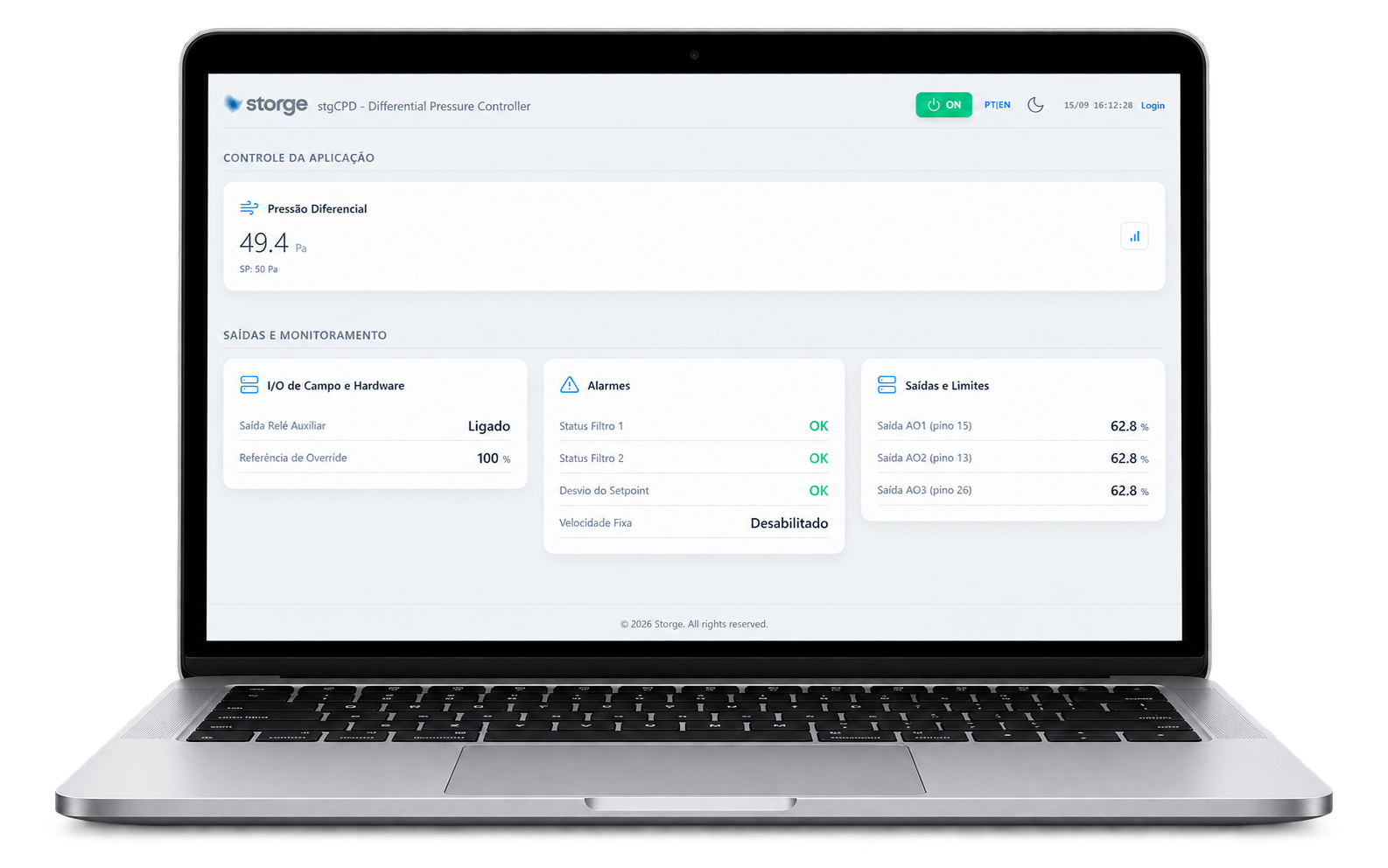
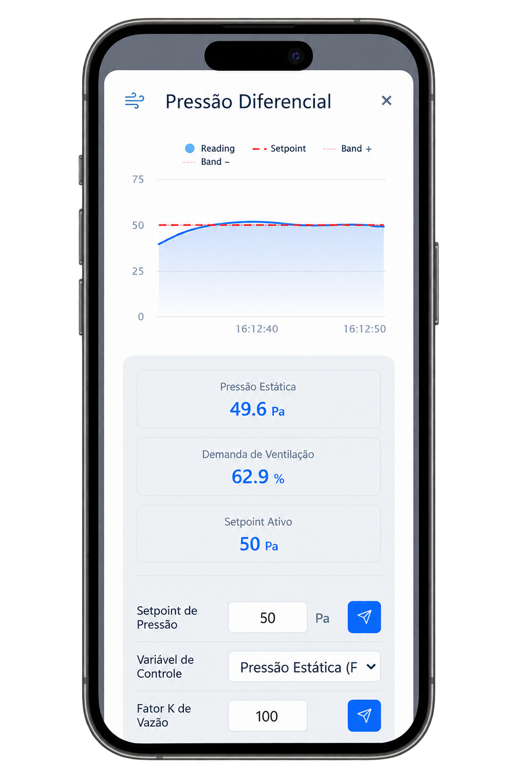
Live reading, setpoint, pressure switch status and analogue outputs on a computer or phone. Over Modbus RS-485, the same data goes to the BMS.

STG line web interface on a computerSTG line web interface on a phone
Technical data

Product specifications.

Pressure range, K-factor parameters and per-version limits are informed by engineering in the quote.

Measurement
Differential pressure by the built-in sensor · Airflow calculated from pressure and the configured K-factor
Digital inputs
2, for external pressure switches, one per filter
Command
To the fan, through a drive compatible with the motor (STG DRV for single-phase AC/EC; frequency drive for three-phase)
Interface
4.3" display and web interface
Communication
Modbus RS-485 · STG wireless network
Versions
Black enclosure, 4.3" display · room or panel
Industrial box · next to the equipment
Location
Next to the ventilation system: pressurised stairwell, ventilation box or duct

STG CPD in your project?

Tell us the application, the planned fan and the filters to monitor. Engineering confirms the configuration and returns the proposal.